
Documentation
This is the official documentation for the Power Watcher v.3, written by Yuriy Logvin.
You can download user manual using the link below:
Device Description
Power Watcher device is used for measurement of a current, voltage, speed, temperature and a number of parameters calculated as functions thereof, e.g. a power, energy consumption rate, number of charge/discharge cycles, mileage, etc.
Application area: electric bicycles, scooters, electro mobiles, electric cars, or other electric transportation means.
Data is indicated via an external device which can be an Android (v4.0 or newer) based smartphone or a tablet capable of supporting Bluetooth2.0.
The device consists of a "hardware" and "software" parts.
The "Hardware" part is a board with microcontroller and embedded firmware, which are connected to the Bluetooth-adapter and sensors measuring the current speed, temperature, voltage.
The "Software" part is a program, which runs on the Android operating system.
"Software" and "hardware" interact with each other via Bluetooth.
| Parameter | Value |
|---|---|
| Min voltage, V | 24 / 10 |
| Max voltage, V | 200 / 600 (for external voltage sensor) |
| Power supply, V | 200 / 36 |
| Min operational temperature, ᴼС | -20 |
| Max operational temperature, ᴼС | 80 |
| Current | Calculated by the sensor |
| Temperature, ᴼС | -55...+125 |
| Operational distance, m | 3...20 |
The device measures the following parameters:
- Current
- Voltage
- Speed
- Temperature (2 sensors)
The device calculates:
- Ampere-hour spent
- Total Ampere-hour spent (during operation of the device)
- Watt-hour spent (Watt-hours when charging is not counted, recuperated - counted)
- Ampere-hour recuperation
- Ampere-hour charged
- Watt-hour recuperation
- Recuperation percentage
- Charge level %
- Charge/discharge cycle count
- Distance
- Distance rest
- Total distance
- Min voltage
- Max voltage
- Мax speed
- Average speed
- Time on the road
Customizable parameters:
- Wheel length
- Number of speed sensor rotation poles
- Current sensor sensitivity
- Battery capacity, AH
- Charged voltage
- Velocity gauge max, Km/H
- Power gauge, min, Watt
- Power gauge, max, Watt
- Current zero temperature correction
- Temp sensor type
- Display power in Kw
Commands:
- Start the new cycle
- Reset current offset to zero
- Reset all stored data
Power Watcher Software
Power Watcher software has 3 screens – “Display”, “All parameters” and “Settings”. You can switch between the screens by swiping left or right.
Screen Descriptions
Main Screen
The “Main screen” solely indicates the selected parameters. It has several “zones”:
- Center. This screen includes the "battery", charge percentage and energy spent. This is a static zone and display parameters in it can't be changed.
- Upper-left. Configurable display area, as well as all subsequent ones.
- Upper-right.
- Center.
- Bottom-left.
- Bottom-center.
- Bottom-right.
All parameters
This screen allows selecting the parameter set to be indicated on the “Display” screen. To specify the parameter position, you need to tap on the parameter, then in the context menu select its place on the display. This screen is scrollable.
Settings
On the “Settings” screen you can specify the wheel length, shunt resistance etc.
Additional Software Features
Main screen parameter selection ¬— tap and hold the parameter that you want to change for at least 2 seconds. Then select the parameter that you want to display on the main screen.
Charge cycle reset — press and hold the battery icon for at least 2 seconds.
Device Variants
By Power Source
Power Watcher can be supplied without a high-voltage converter, for use in low-voltage (up to 36 V) devices or to be powered from the onboard 12V network (in this case, the voltage is measured using an external RS485 device).
The device in this case is called PowerWatcher3LV (low voltage).
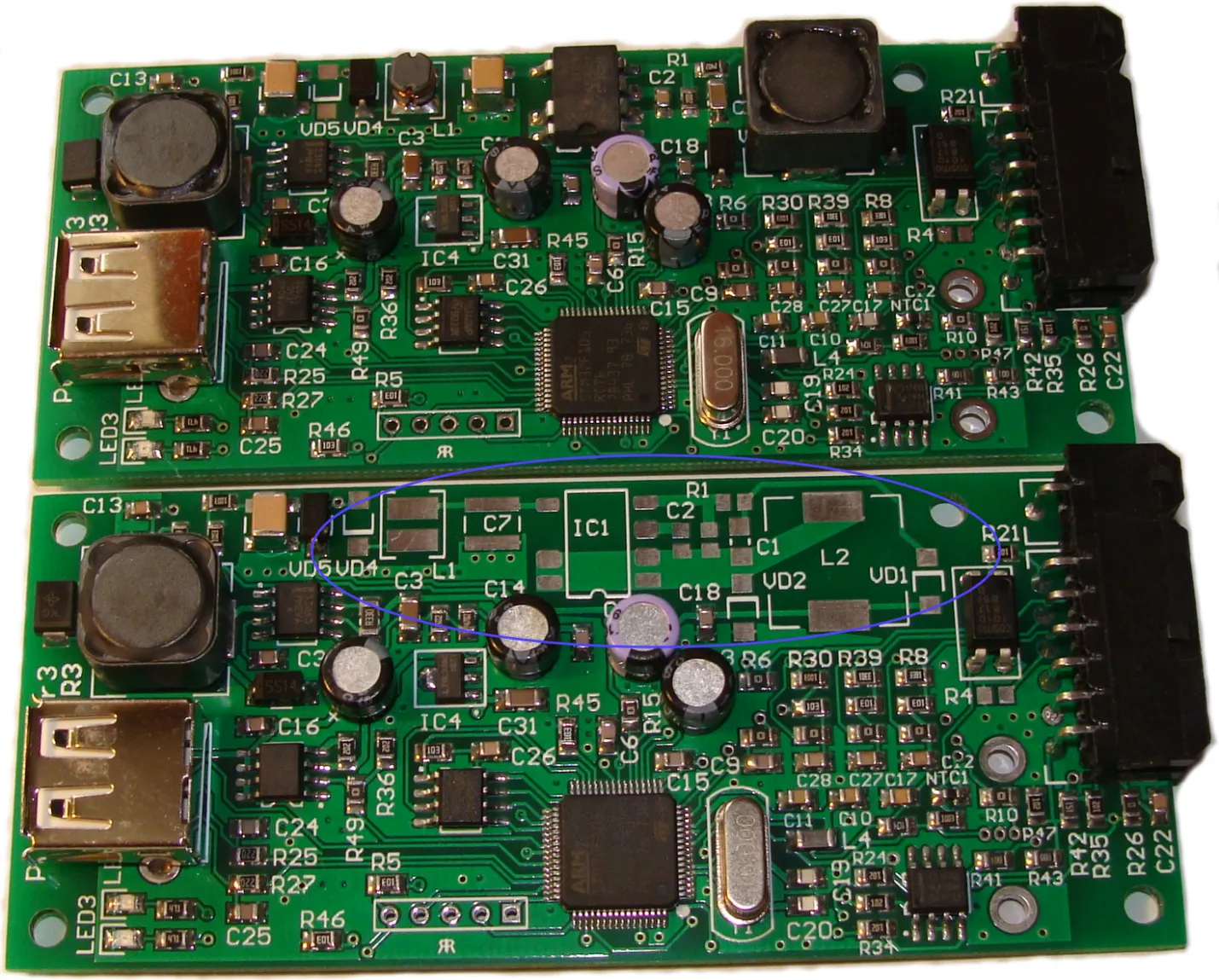
The photo below shows the device with and without a converter. The pinout of the VD4 and VD5 diodes determines where the 12 volt cascade will be powered from. This means that by purchasing a board with a soldered high-voltage cascade, moving the diode from VD4 to VD5, we get a device with a power range of up to 36 volts instead of 200.
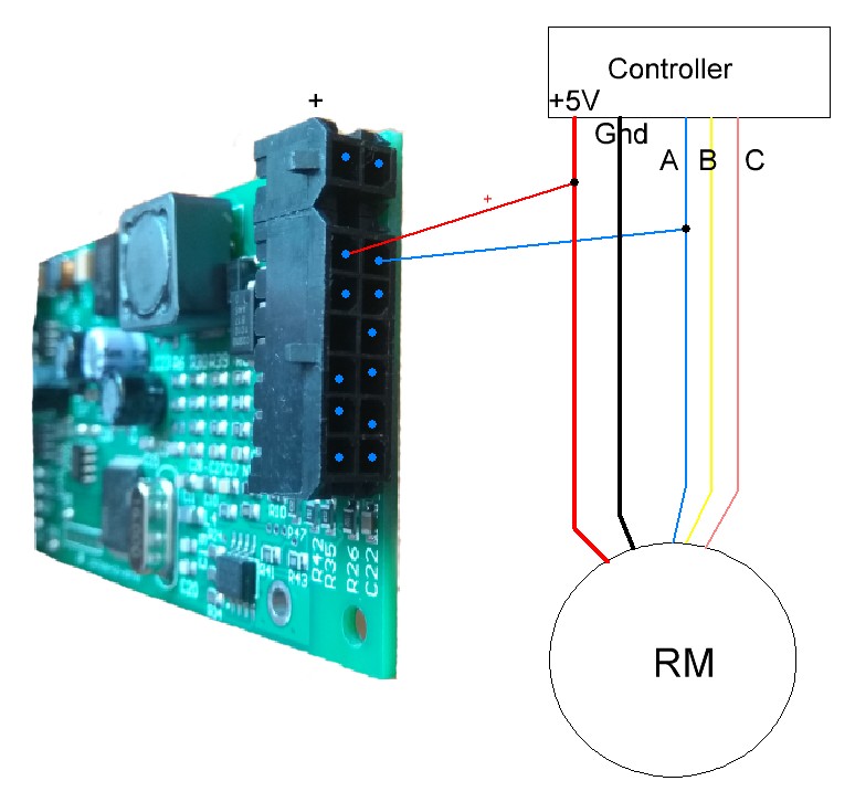
Connecting the Sensors
The device must be connected to the current sensor, battery, thermo resistor and the speed sensor.
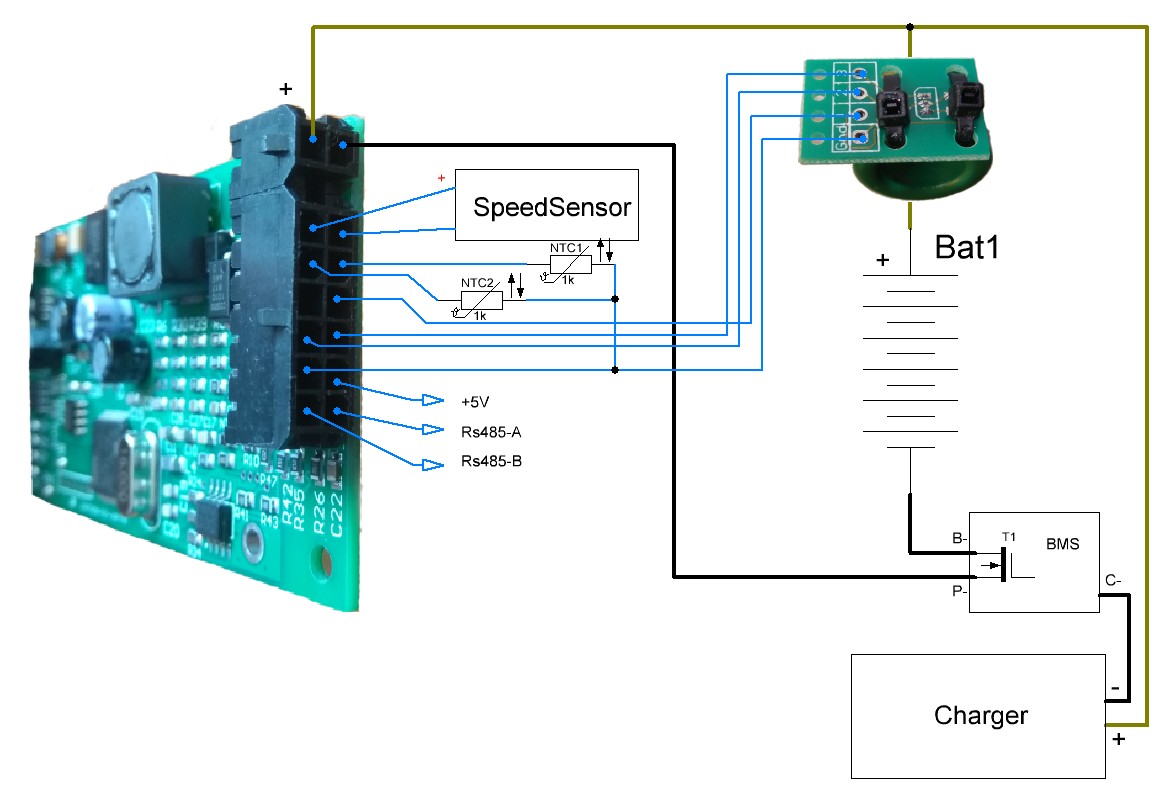
- NTCM-3.3K thermo resistors. NTC1 and NTC2 on the scheme.
- Current sensor. As a current sensor, an analog Hall Effect sensor is usually used. It is connected as shown on the scheme. Digital sensor can be used instead of analog.
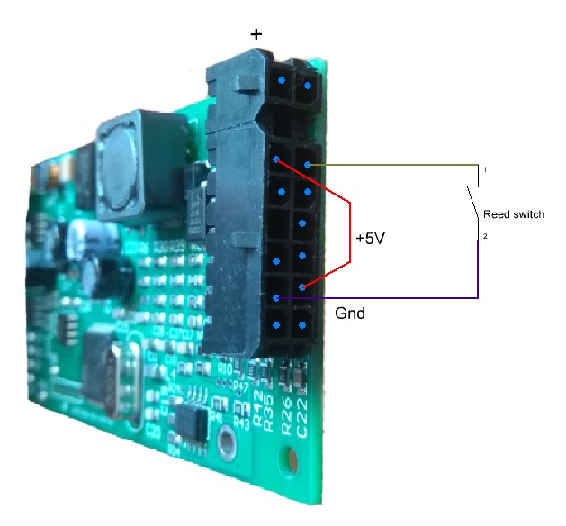
- Speed sensor — it’s a simple reed switch. Or any sensor with the open collector transistor on output (such as a digital Hall sensor). Various ways of connecting the speed sensor will be described below.
- Digital sensors. Digital current and voltage sensors as well as the screen are connected to the RS485 bus.
The Speed Sensor
An optocoupler is installed at the input of the PW speed signal. This allows us to quite flexibly connect the speed sensor.

There are several connection variants.
- On the electric bike to one of the hall sensors of the motor-wheel.
- Separate sensor which is used only by the Power Watcher.
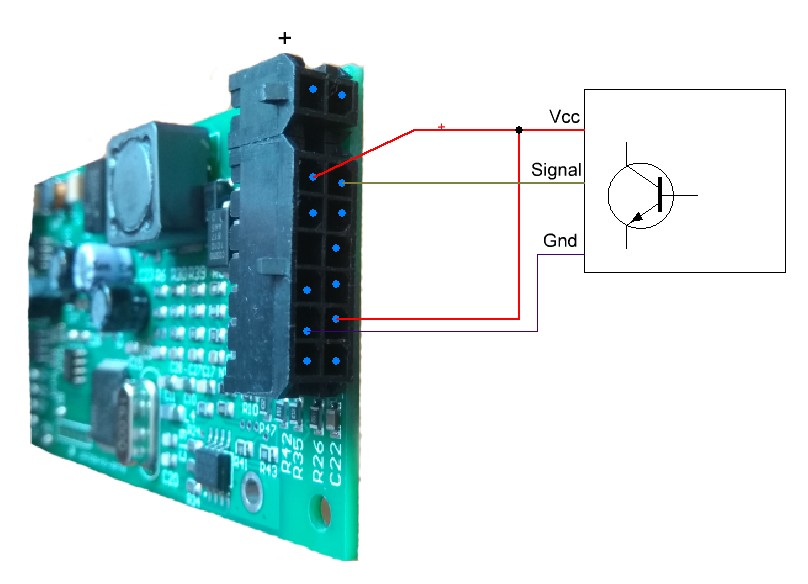
- Reed switch.
The Current Sensor
Current sensors of two types can be used: analog or digital. There are 3 kinds of them: built-in analog, external analog, external digital.
Built-in is soldered into the board of the device and allows to measure currents up to 140A. To measure high currents, an external sensor should be used.
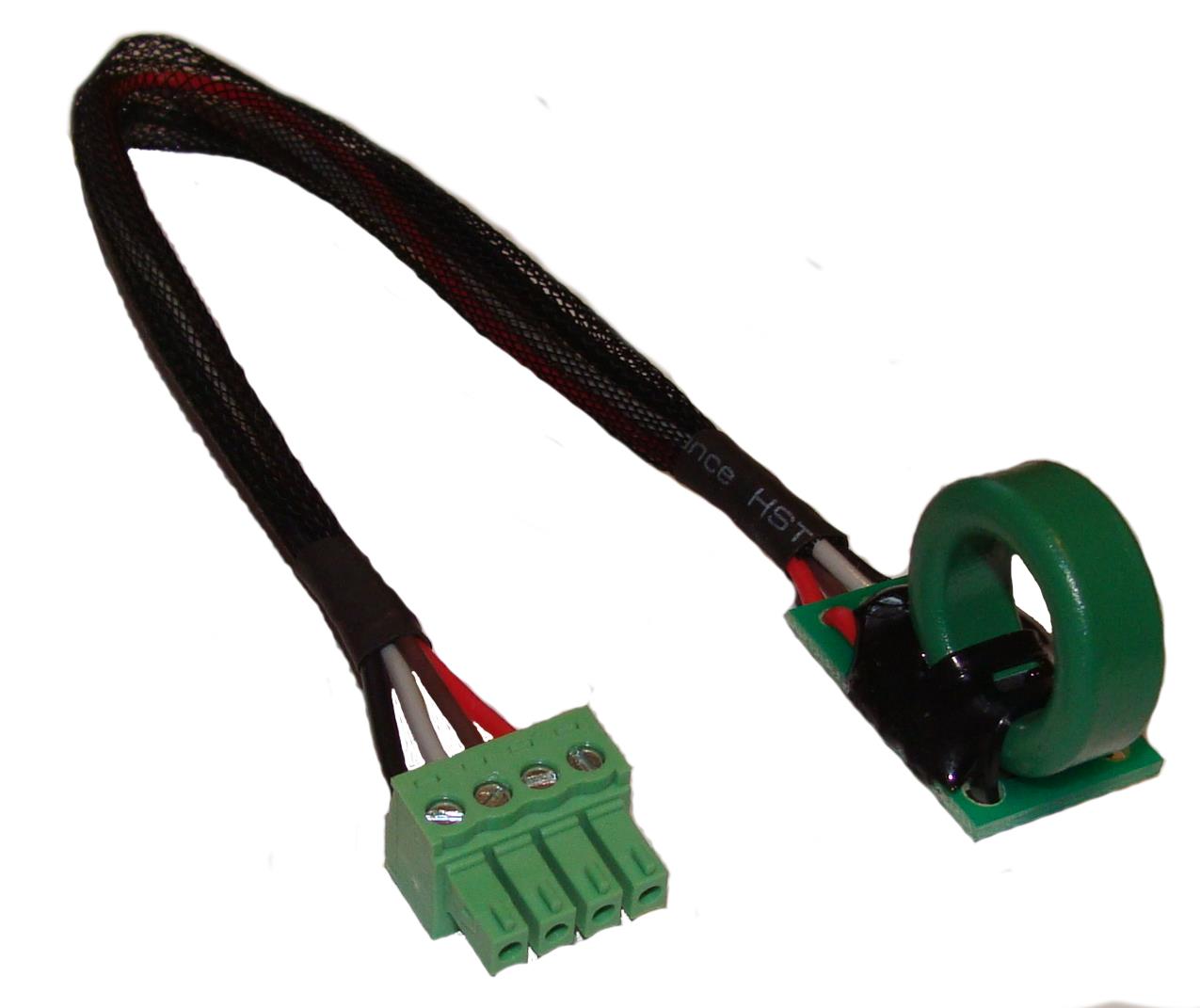
PW-SS49E-CORE Sensor
This sensor is based on the analog Hall sensor SS49E. The sensor measures the current that flows through the ring. It is shown on the photo below.
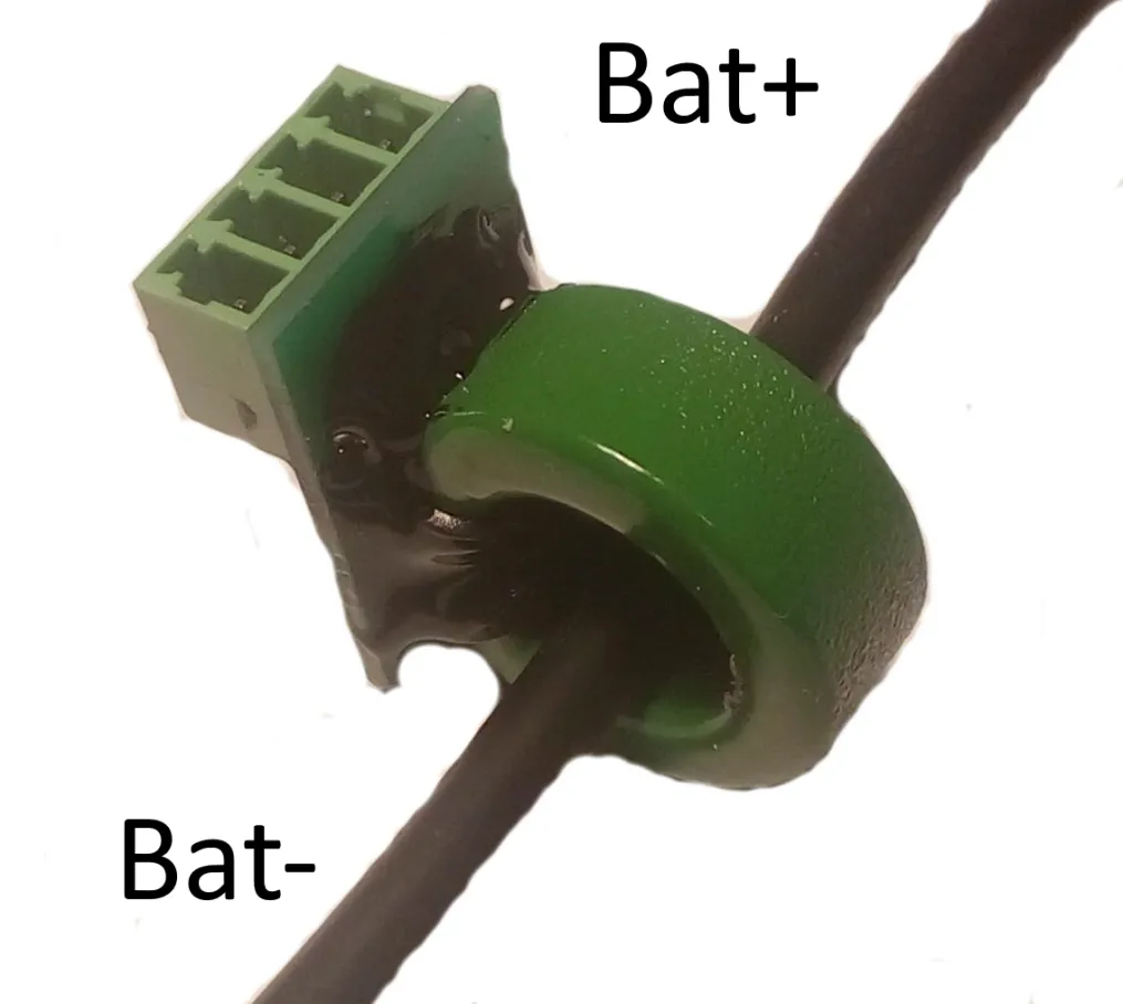
Where “Bat-” — negative terminal of the battery.
And “Load” — load.
Wire pinout is the same as for “PW-ACS75X” sensor.
IMPORTANT! For this sensor in the settings you need to specify:
- Coefficient of temperature zero current correction— the value of the correction factor is indicated on the sensor.
- Current sensor sensitivity — depends on the width of the cut in the ferrite ring. The cut value is indicated on the inner surface of the ring in the process of manufacturing.
| Gap, mm | Value, mkV/A | Measured currents, A |
|---|---|---|
| 2,5 | 9000 | ±170 |
| 3 | 7000 | ±220 |
| 4,3 | 5000 | ±320 |
| 5 | 4000 | ±400 |
| 6 | 3500 | ±450 |
| 6,7 | 3000 | ±500 |
Explanations: Each current sensor contains a thermal sensor. When a current is set to zero, the voltage at the output of the sensor, which corresponds to zero current and temperature, is stored. During current measurements, zero drift correction is performed depending on temperature.
PW-SS49E-CW Sensor
This sensor is almost identical to “PW-SS49E-CORE”, and differs from the latter only in that the wires are soldered to the sensor board.
PW-SS49E Sensor
This sensor is almost identical to “PW-SS49E-CORE”. And it differs from the latter by the absence of a ferrite magnetic field concentrator ring.
For the sensor to work correctly, the magnetic field lines must cross the plane of the sensor body along a normal (perpendicular). See the photo below.
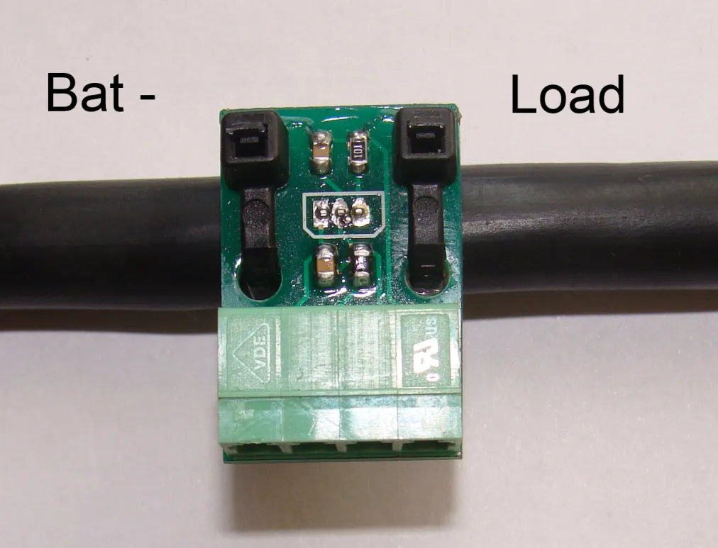
Where “Bat-” — negative terminal of the battery.
And “Load” — load.
See the PW-SS49E-CORE sensor description for details.
Temperature sensors
The device can be used with 2 temperature sensors.
As a first sensor, 3 variants are possible:
- N110K003.30 (NTC 3.3k)
- KTY83
- KTY84
As a second sensor — only N110K003.30.
Setting Up The Device
- Power on the device.
- Pair Android device with the Power Watcher. The pin code is “0000”.
- On the "Settings" page (you can switch between pages with a swipe) set the following parameters:
- Wheel Length.
- Current sensor sensitivity. The calculation of this value is described in the "Current sensor" chapter.
- Battery Capacity.
- Charged Voltage. The value must be less than voltage at the end of the charge by 0.5-1V.
- Reset current offset to zero.
- Return to the previous pages is done with the "Return" button.
Operation Algorithm
To calculate the correct energy values, device must be active both during charge and during discharge.
During the charge process, if the battery output voltage is higher than parameter «Charged Voltage», this means that the charging process has finished.
When this condition occurs, the values of distance, spent energy, average and maximum values of speed, current and voltage are cleared.
Power level is set to 100%.
The battery charge level is calculated based on the total capacity in Ampere-hours and Ampere-hours spent.
Software Update
The software can be updated from the USB-flash drive.
USB-flash must have only one volume and formatted in FAT32.
The sequence of steps to update the firmware:
- Copy the firmware file to the root of the USB-flash drive. (Example: "pwu_2_02.em1")
- Power off the device.
- Connect USB-flash instead of the Bluetooth-adapter.
- Turn on the power.
- The blue LED should start to blink - it means that the process of firmware update is in progress.
- Upon completion of the firmware update, the two LED (blue and red) are lit.
- Disconnect USB-flash. LEDs should go out.
- Connect Bluetooth-adapter.
On error, red and blue LEDs will be flashing alternately: once the red one, N-times the blue one. Where N - the error code.
Error codes:
- 1 — waiting for the USB-device connection
- 2 — usb-flash has no new firmware
- 3 — usb-flash has no firmware
- 5 — can’t read the firmware file
- 6 — firmware file header read error
- 7 — incorrect firmware file signature